ابزار Xhorse VVDI
Xhose VVDI نرم افزار برنامه نویس اصلی و سخت افزارابزار Xhorse VVDI
Xhose VVDI نرم افزار برنامه نویس اصلی و سخت افزارRead BMW MSV90 DME with Xhorse Multi Prog
How-to: read and write BMW X3 MSV90 DME using Xhorse Multi Prog programmer on bench.
Read ok, write OK, checksum by multi-prog.
Steps:
Reading information from the old computer:
Select ALL from the menu.
Choose IMMOBILIZER.


Read the computer’s serial number.
Select the corresponding option and press OK.
Choose BENCH to read the information without removing the computer.
Follow the schematic to connect the cables.


Click on EEBROM to read the memory.
Click on FLASH to read the file.
Click on OPEN then VERIFY to ensure the file’s integrity.
Click OK to start writing.
Wait until the percentage reaches 100%.


Writing information to the new computer:
Select ALL from the menu.
Choose IMMOBILIZER.
Write the serial number of the new computer.
Select the corresponding option and press OK.
Choose BENCH to write the information without removing the computer.
Follow the schematic to connect the cables.
Click on EEBROM to write the memory.
Click on FLASH to write the file.
Click on OPEN then WRITE to write the file.
Wait until the percentage reaches 100%.

Starting the car:
Connect the new computer to the car. Start the car.
Notes:
Make sure to use the Xhorse MULTI BROG software version 1.44 or later. Ensure proper cable connections. Verify file integrity before writing. With these simple steps, you can successfully transfer information from an old BMW computer to a new one.
Xhorse Condor II Error Code 42 Solution
Problem:
I got error code 42 when decoding HU83 key blank with xhorse condor ii key cutting machine.
I have cleaned several times Also made calibration again Still same. Any advice?


Solution:
As the condor ii said, probe and cutter are not at same height.
Clean the probe/cutter or do a height level adjustment.
How to do height level adjustment?
•Click Device Info at the bottom
•then click “Height Level Adjustment”
•Next you will want to READ the onscreen directions and follow them exactly.
Feedback:
It works after adjusting height level.
Xhorse Dolphin XP005 Gen1 Replacement Manual
Here comes the Xhorse Dolphin XP005 (Generation 1) automotive key cutting machine maintenance manual.
This manual applies to models with serial number KM06, KM12 of Dolphin Generation I model.
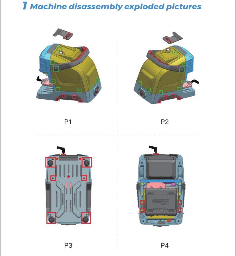
1.Machine disassembly exploded pictures
P1-P10 location
2 Method of replacing parts due to machine malfunction
2.1 Replace the battery
Please refer to the disassembly pictures P1, P2, P3, and P4 in Chapter 1. Unscrew the screws in the red box separately to replace the battery module with a new one, and plug in the three wirings ports of the battery accordingly.
2.2 Replace the mainboard
Reason of replacement:1. The cutter is non-conductive 2.Unable to charge 3.Unable to power on or upgrade. 4. LED light does not light up 5. Startup error 6. Cutting error.
Please refer to the disassembly pictures P1 and P2 in Chapter 1.
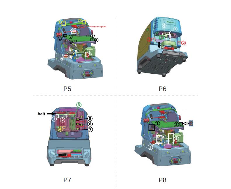
Remove the screws in the green frame to remove the rear cover. Then refer P5 to remove the screws at position Z of the white frame at ⑩, and then remove the screws in the black frame at ① to ⑤ separately to replace the mainboard with a new one. Insert the mainboard port according to the wire harness label.
2.3 Replace the LED screen
Please refer to the disassembly pictures P1 and P2 in Chapter 1.
Remove the screws in the green frame separately to remove the rear cover. Then refer P5 to remove the screws in the yellow frame at ⑥⑦, and then rotate the Z-axis in the red circle clockwise to its highest position, refer P6 to pulldown the protective cover in the direction of the black arrow, rotate the column in the green box at ⑤to the left and remove it, then remove the rubber plug from the red box at ①② and unscrew the screw, and remove the front cover and screen and replace them. Insert the mainboard port according to the wire harness label.2.4 Replace the spindle motor beltDue to long-terms use, the belt should be replaced in a timely manner when it ages, breaks or slips(breaking the cutter during cutting). Refer Chapter 2.3 to remove the front cover to see the belt (shown in P7), and replace it directly.
2.5 Replace the motor
2.5.1 Replace the spindle motor
When the motor makes abnormal noise, it needs to be replaced. Refer chapter 2.3 to remove the front cover and belt, then refer P7 to unscrew the screws in the white frame at ①② and green frame at ③, after that, replace it directly.
2.5.2 Replace the X-axis screw shaft motor
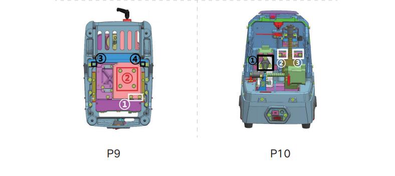
When the screw motor gets stuck or bent, the X-axis screw shaft motor need to replace. Refer to the disassembly pictures P1 and P2 in Chapter 1, remove the screws in their green frame separately to remove the rear cover, refer P8 to remove the screws in the white frame at ③④, after that, replace it directly.To replace the x-axis rail need to refer to chapter 2.1. Remove the battery first, then refer P9 to remove the screws in the white frame at ①, then remove screws in the red frame at ② and the black screwsat③④, after that, replace it directly.
2.5.3 Replace the Y-axis screw shaft motor
When the screw motor gets stuck or bent, the Y-axisscrew shaft motor need to replace. Refer chapter 2.2 to remove the mainboard first, then refer P8 to remove thescrews in the black frame at ①② and the white frame at③④, remove the X-axis screw shaft motor first, then refer P10 to remove the screws in the black frame at ①, remove the screws in the red circle in the right picture , then replace the Y-axis screw shaft motor directly.
2.5.4 Replace the Z-axis screw shaft motor
When the screw motor gets stuck or bent, the Z-axis screw shaft motor needs to replace. Refer to the chapter2.2 to remove the mainboard first, refer P8 to remove thescrews in the black frame at ①②, then refer P10 to remove the screw in the white frame at②③, remove thescrews in the red circle in the right picture, then replace the Y-axis screw shaft motor directly.
2.6 Replace the sensor
2.6.1 Replace the X-axis sensor
When the sensor is defective or damaged, it needs to be replaced. Please refer P1 and P2 to remove the screws in the green frame and remove the rear cover, then refer P5 to remove the screws in the white frame at ⑧, then replace it. Insert the mainboard port according to the wire harness label.
2.6.2 Replace the Y-axis sensor
When the sensor is defective or damaged, it needs to be replaced. Please refer P1 and P2 to remove the screws in the green frame and remove the rear cover, then refer P5 to remove the screws in the white frame at ⑨, then replace it. Insert the mainboard port according to the wire harness label.
2.6.3 Replace the Z-axis sensor
When the sensor is defective or damaged, it needs to be replaced. Please refer P1 and P2 to remove the screws in the green frame and remove the rear cover, then refer P5 to remove the screws in the white frame at ⑩, then replace it. Insert the mainboard port according to the wire harness label.
2.7 Replace or inspect the probe wires
2.7.1 The probe non-conductive
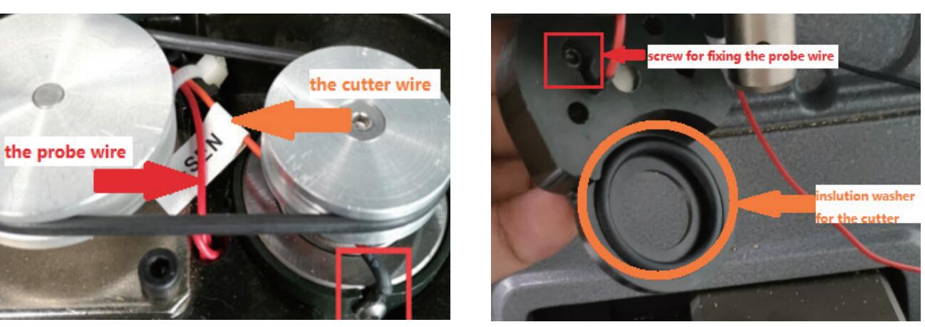
Poor contact or broken circuit caused by worn probe wires. Refer chapter 2.3 to remove the front cover and belt, then refer P7 to remove the green frame at③, refer P6 to remove the white frame at③④. As shown in the left picture below, gently pull the red probe wire forward while shaking the probe base. Then in the right picture below, you can see the screw which fixed probe in the red frame, unscrew it to replace the probe and cutting wires. Insert the mainboard port according to the wire harness label.
2.7.2 The probe remains conductive
Refer to chapter 2.7.1, check if the probe wire is broken, and if there are metal debris near the fixingscrews or at the lamp panel (don’t blow with an air gun).
2.8 Replace or inspect the cutter wires
2.8.1 The cutter non-conductive
Poor contact or broken circuit caused by worn probe wires, refer chapter 2.7.1 to replace the probe and cutting wires. Insert the mainboard port according to the wire harness label.
2.8.2 The cutter remains conductive
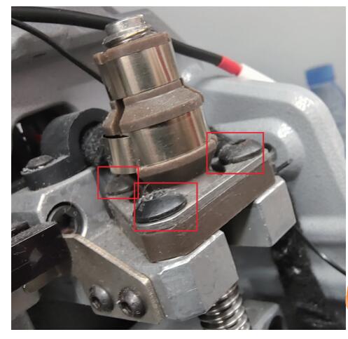
Refer to chapter 2.7.1, check if the cutter wire isbroken, and if there are metal debris near the fixing screws or at the lamp panel (don’t blow with an air gun).If none of the above situations exist, the cutter remains conductive, refer P7 to loosen the screws in the black frame at⑤⑥⑦, and tighten the screws in the red frame at⑧⑨, use your fingers to push the cutter hole upwards slowly, then observe if the white insulation paper is broken or if there are metal debris inside the cutting shaft (don’t blow with an air gun), refer to the picture on the right. when reinstalling the screws, it is necessary to refer P7 to loosen the screws in the red frame at⑧⑨ first.
2.9 Replace the probe shaft or the cutter shaft
When the top thread of the probe and the cutter is slippery and cannot be removed, it is necessary to replace the probe shaft or the cutter shaft. To replace the probe shaft needs to refer chapter 2.7.1 and replace the probe base. Replace the cutter shaft needs to refer chapter 2.8 and remove the cutter shaft, then refer chapter 2.10 to disassemble it.
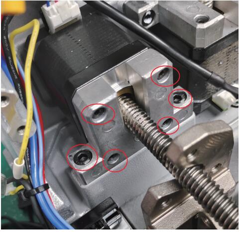
2.10 Main shaft abnormal noise maintenance
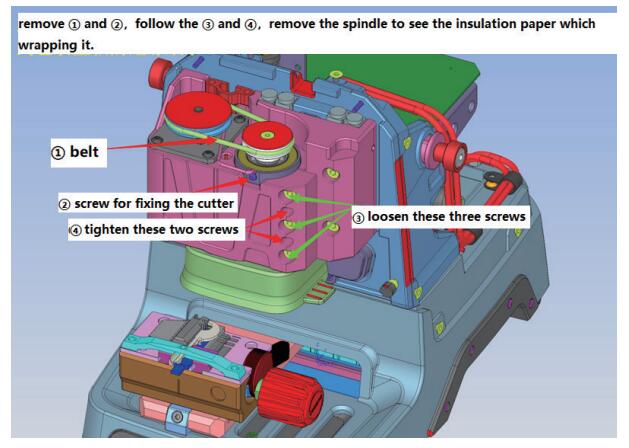
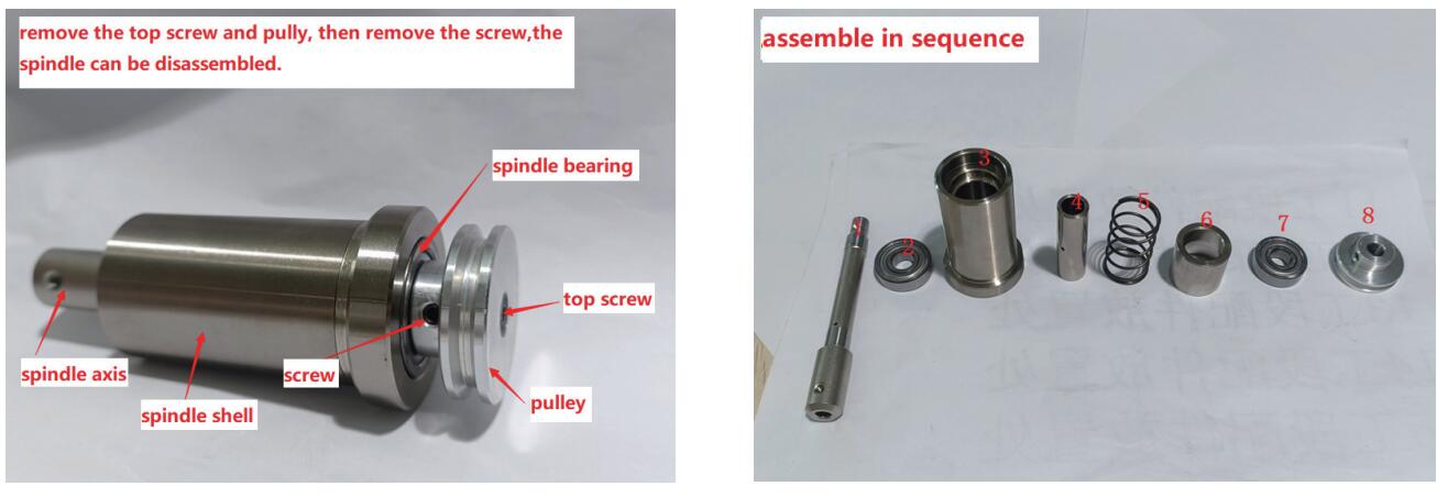
reason for abnormal noise: metal debris present, belt wear and large gap in the shaft hole for the cutter. Refer chapter 2.3 to remove the front cover, clean the metal debris, replace the belt, or refer P7 to loosen the screws in the red frame at⑧⑨, and tighten the screws in the black frame at⑤⑥⑦.The disassembly and assembly of the spindle structure are as follows:
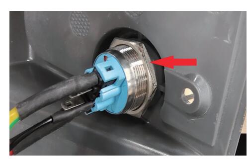
2.11 Replace the key switch and USB port
Replace the key switch should refer to the disassembly pictures P1 and P2 in Chapter 1. Remove the screws inthe green frame to remove the rear cover. Unscrew the nut indicated by the arrow to replace it. Then insert the mainboard port according to the wire harness label.
Replace the USB port should refer the picture below, remove the screws in the black frame, then remove the screws in the red frame. After replacement, insert the mainboard port according to the wire harness label.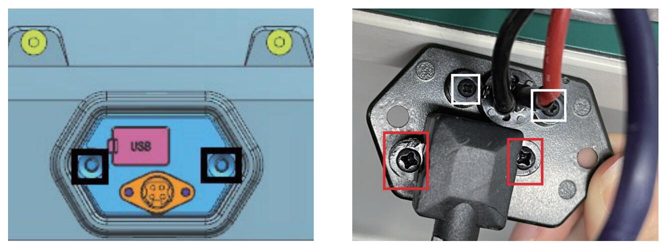
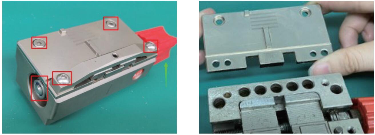
2.12 Replace clamp parts
M1 clamp: Remove the screws and nut in the red frame on the left picture, push the knob up, then you can replace the clamp surface.
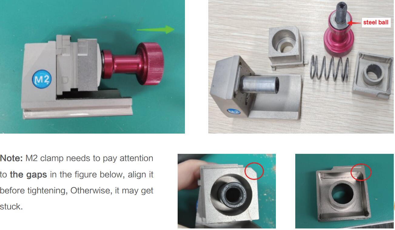
M2 clamp: Rotate the knob outward on the left picture, then it can be disassembled. Replace the corresponding parts according to the picture on the right.
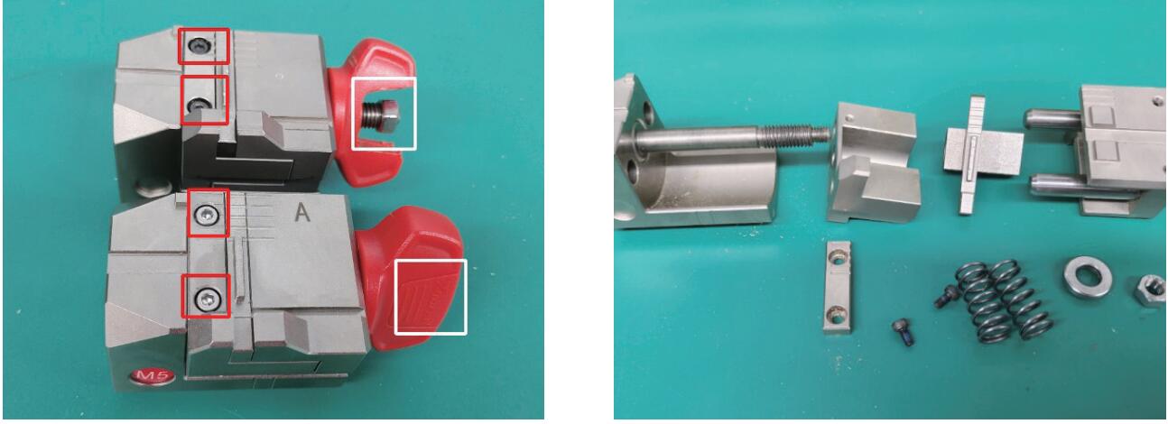
M5 clamp:Remove the nut in the white frame and remove the screws in the red frame on the picture below, rotate the knob outward on the left picture, then it can be disassembled. Replace the corresponding parts according to the picture on the right.
Xhorse Condor XC-002 Pro Review What is Good
Xhorse Condor XC-002 Pro is the 2024 latest key cutting machine that I’ve got today. The machine is large and massive but simply excellent. When I took it in my hands, I realized that this was the best machine that I had. Now I’ll try to make a quick review for your guys.
.jpg)
The clamp is fixed by simply turning. I found there are 3 positions: A/B/C. Once I chose a well position, it’ll just be a convenient distance to the nearest vice. We generally clamp it with just one turn.
And then, what can these vices do? They can cut at any angles.
For example, to cut English-type keys or car keys. Inserted, clamped, set and cut accordingly key wave.
We take similar keys in which they are angular, the holes are made at an angle. The side clamp is suitable for this. We can set the desired angle and start cutting.
.jpg)
.jpg)
.jpg)
.jpg)
.jpg)
The clamp has a feat on itself and it fixes it from moving like this. This is such a convenient design.
Instead of the usual hexagonal clamp, to replace the cutter, you literally need to put the right one in a second and tighten it back. And the cutter is in.
Here shows the switching mode to the hole pattern.
There’s an adjustment, electronic adjustment, alignment of the cutter, and it even shows which way to turn. Now it shows screw it in. Here, bring it this direction. The green light is on, the cutter is set.
When you work with the keys, you don’t need to turn on and off button. The machine turns on automatically when lowered. The handle here is used to adjust the speed. Handle these quick-release cutters is just the second change. No need to click on or off the button. Just pull the handle down, then it worked and instantly adjust the positions of the vice.
In the planes, you don’t need to unscrew anything to tighten. It’s all done simply with your fingers. It’s very convenient. Everything is cool and the price will also be great.
.jpg)
.jpg)
.jpg)
Besides, there’s something in the side clamp. You can clamp such a key with this one. If it interferes, just insert it to the opposite direction. The clamp is very functional. In principle, most key types can be fit on.
The Condor XC-002 Pro booklet is clear. Here are what we can get from the package: a brush, 1 probe, 2 cutters, several stops and spacers for better clamping.
That’s all today’s review.
.jpg)
.jpg)
https://www.vvdishop.com/service/xhorse-condor-xc-002-pro-review.html
Tipt to Cut B119 Key Blank with Xhorse Dolphin XP005
Problem:
My friend has problems with the Xhorse dolphin xp005 key cutting machine. It’s not cutting b119 keys correctly. They look identical but only turn on door and not ignition.

Here are possible solutions:
1. Do a recalibrating. Recalibration should handle it,
Go into the app and calibrate it. Just did a couple b119 keys and it’s doing fine. Usually calibrate Dolphin once a month to stay on the safe side.
2. Make sure the original key if decoding from it with the machine that the key blade is clean of any dirt or debris this can cause a issue with improper read which results in only working one lock and not another.
3. Try universal duplication.
4. Upgrade to m5 clamp.
User Feedback:
Did recalibration. No luck. Change M5 clamp and M5 clamp worked.