ابزار Xhorse VVDI
Xhose VVDI نرم افزار برنامه نویس اصلی و سخت افزارابزار Xhorse VVDI
Xhose VVDI نرم افزار برنامه نویس اصلی و سخت افزارXhorse Dolphin XP005 Gen1 Replacement Manual
Here comes the Xhorse Dolphin XP005 (Generation 1) automotive key cutting machine maintenance manual.
This manual applies to models with serial number KM06, KM12 of Dolphin Generation I model.
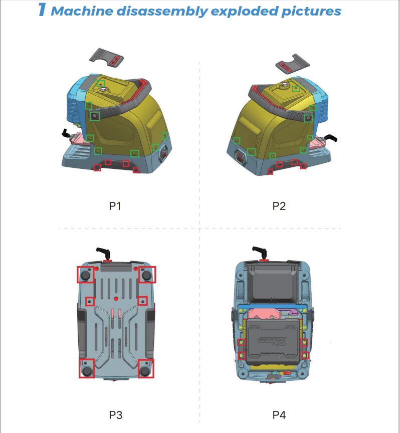
1.Machine disassembly exploded pictures
P1-P10 location
2 Method of replacing parts due to machine malfunction
2.1 Replace the battery
Please refer to the disassembly pictures P1, P2, P3, and P4 in Chapter 1. Unscrew the screws in the red box separately to replace the battery module with a new one, and plug in the three wirings ports of the battery accordingly.
2.2 Replace the mainboard
Reason of replacement:1. The cutter is non-conductive 2.Unable to charge 3.Unable to power on or upgrade. 4. LED light does not light up 5. Startup error 6. Cutting error.
Please refer to the disassembly pictures P1 and P2 in Chapter 1.
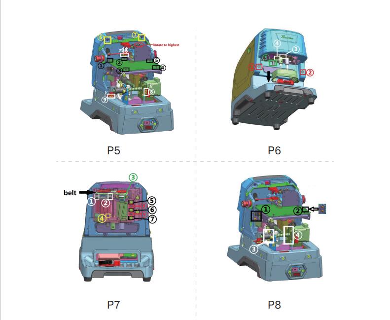
Remove the screws in the green frame to remove the rear cover. Then refer P5 to remove the screws at position Z of the white frame at ⑩, and then remove the screws in the black frame at ① to ⑤ separately to replace the mainboard with a new one. Insert the mainboard port according to the wire harness label.
2.3 Replace the LED screen
Please refer to the disassembly pictures P1 and P2 in Chapter 1.
Remove the screws in the green frame separately to remove the rear cover. Then refer P5 to remove the screws in the yellow frame at ⑥⑦, and then rotate the Z-axis in the red circle clockwise to its highest position, refer P6 to pulldown the protective cover in the direction of the black arrow, rotate the column in the green box at ⑤to the left and remove it, then remove the rubber plug from the red box at ①② and unscrew the screw, and remove the front cover and screen and replace them. Insert the mainboard port according to the wire harness label.2.4 Replace the spindle motor beltDue to long-terms use, the belt should be replaced in a timely manner when it ages, breaks or slips(breaking the cutter during cutting). Refer Chapter 2.3 to remove the front cover to see the belt (shown in P7), and replace it directly.
2.5 Replace the motor
2.5.1 Replace the spindle motor
When the motor makes abnormal noise, it needs to be replaced. Refer chapter 2.3 to remove the front cover and belt, then refer P7 to unscrew the screws in the white frame at ①② and green frame at ③, after that, replace it directly.
2.5.2 Replace the X-axis screw shaft motor
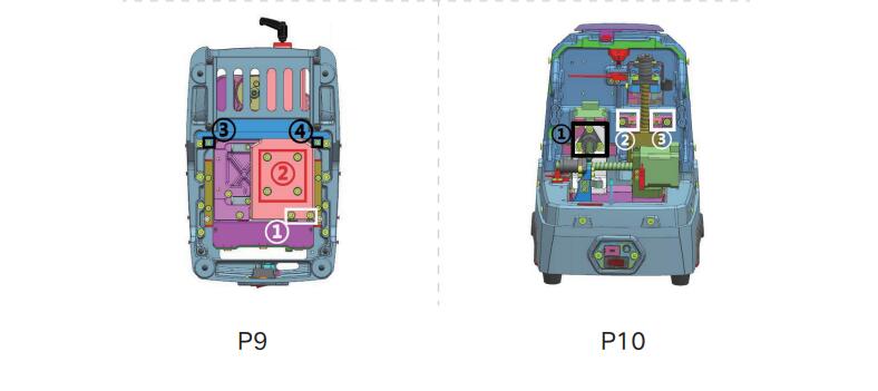
When the screw motor gets stuck or bent, the X-axis screw shaft motor need to replace. Refer to the disassembly pictures P1 and P2 in Chapter 1, remove the screws in their green frame separately to remove the rear cover, refer P8 to remove the screws in the white frame at ③④, after that, replace it directly.To replace the x-axis rail need to refer to chapter 2.1. Remove the battery first, then refer P9 to remove the screws in the white frame at ①, then remove screws in the red frame at ② and the black screwsat③④, after that, replace it directly.
2.5.3 Replace the Y-axis screw shaft motor
When the screw motor gets stuck or bent, the Y-axisscrew shaft motor need to replace. Refer chapter 2.2 to remove the mainboard first, then refer P8 to remove thescrews in the black frame at ①② and the white frame at③④, remove the X-axis screw shaft motor first, then refer P10 to remove the screws in the black frame at ①, remove the screws in the red circle in the right picture , then replace the Y-axis screw shaft motor directly.
2.5.4 Replace the Z-axis screw shaft motor
When the screw motor gets stuck or bent, the Z-axis screw shaft motor needs to replace. Refer to the chapter2.2 to remove the mainboard first, refer P8 to remove thescrews in the black frame at ①②, then refer P10 to remove the screw in the white frame at②③, remove thescrews in the red circle in the right picture, then replace the Y-axis screw shaft motor directly.
2.6 Replace the sensor
2.6.1 Replace the X-axis sensor
When the sensor is defective or damaged, it needs to be replaced. Please refer P1 and P2 to remove the screws in the green frame and remove the rear cover, then refer P5 to remove the screws in the white frame at ⑧, then replace it. Insert the mainboard port according to the wire harness label.
2.6.2 Replace the Y-axis sensor
When the sensor is defective or damaged, it needs to be replaced. Please refer P1 and P2 to remove the screws in the green frame and remove the rear cover, then refer P5 to remove the screws in the white frame at ⑨, then replace it. Insert the mainboard port according to the wire harness label.
2.6.3 Replace the Z-axis sensor
When the sensor is defective or damaged, it needs to be replaced. Please refer P1 and P2 to remove the screws in the green frame and remove the rear cover, then refer P5 to remove the screws in the white frame at ⑩, then replace it. Insert the mainboard port according to the wire harness label.
2.7 Replace or inspect the probe wires
2.7.1 The probe non-conductive
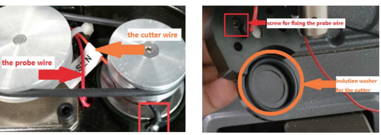
Poor contact or broken circuit caused by worn probe wires. Refer chapter 2.3 to remove the front cover and belt, then refer P7 to remove the green frame at③, refer P6 to remove the white frame at③④. As shown in the left picture below, gently pull the red probe wire forward while shaking the probe base. Then in the right picture below, you can see the screw which fixed probe in the red frame, unscrew it to replace the probe and cutting wires. Insert the mainboard port according to the wire harness label.
2.7.2 The probe remains conductive
Refer to chapter 2.7.1, check if the probe wire is broken, and if there are metal debris near the fixingscrews or at the lamp panel (don’t blow with an air gun).
2.8 Replace or inspect the cutter wires
2.8.1 The cutter non-conductive
Poor contact or broken circuit caused by worn probe wires, refer chapter 2.7.1 to replace the probe and cutting wires. Insert the mainboard port according to the wire harness label.
2.8.2 The cutter remains conductive
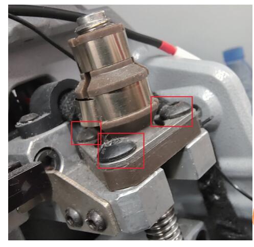
Refer to chapter 2.7.1, check if the cutter wire isbroken, and if there are metal debris near the fixing screws or at the lamp panel (don’t blow with an air gun).If none of the above situations exist, the cutter remains conductive, refer P7 to loosen the screws in the black frame at⑤⑥⑦, and tighten the screws in the red frame at⑧⑨, use your fingers to push the cutter hole upwards slowly, then observe if the white insulation paper is broken or if there are metal debris inside the cutting shaft (don’t blow with an air gun), refer to the picture on the right. when reinstalling the screws, it is necessary to refer P7 to loosen the screws in the red frame at⑧⑨ first.
2.9 Replace the probe shaft or the cutter shaft
When the top thread of the probe and the cutter is slippery and cannot be removed, it is necessary to replace the probe shaft or the cutter shaft. To replace the probe shaft needs to refer chapter 2.7.1 and replace the probe base. Replace the cutter shaft needs to refer chapter 2.8 and remove the cutter shaft, then refer chapter 2.10 to disassemble it.
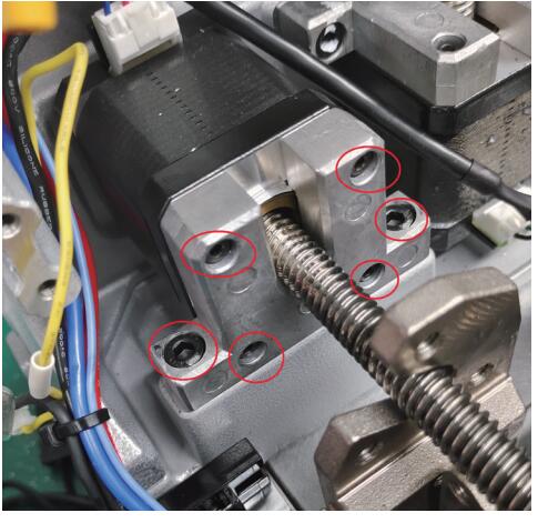
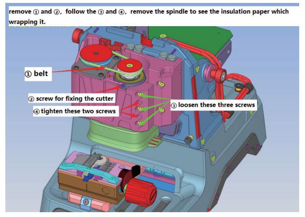
2.10 Main shaft abnormal noise maintenance
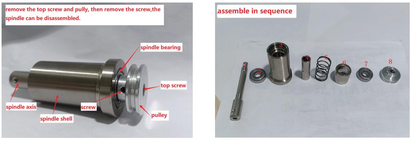
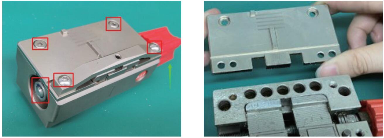
reason for abnormal noise: metal debris present, belt wear and large gap in the shaft hole for the cutter. Refer chapter 2.3 to remove the front cover, clean the metal debris, replace the belt, or refer P7 to loosen the screws in the red frame at⑧⑨, and tighten the screws in the black frame at⑤⑥⑦.The disassembly and assembly of the spindle structure are as follows:
2.11 Replace the key switch and USB port
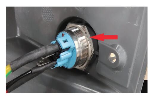
Replace the key switch should refer to the disassembly pictures P1 and P2 in Chapter 1. Remove the screws inthe green frame to remove the rear cover. Unscrew the nut indicated by the arrow to replace it. Then insert the mainboard port according to the wire harness label.
Replace the USB port should refer the picture below, remove the screws in the black frame, then remove the screws in the red frame. After replacement, insert the mainboard port according to the wire harness label.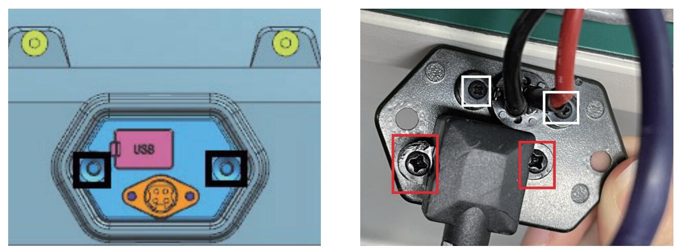
2.12 Replace clamp parts
M1 clamp: Remove the screws and nut in the red frame on the left picture, push the knob up, then you can replace the clamp surface.
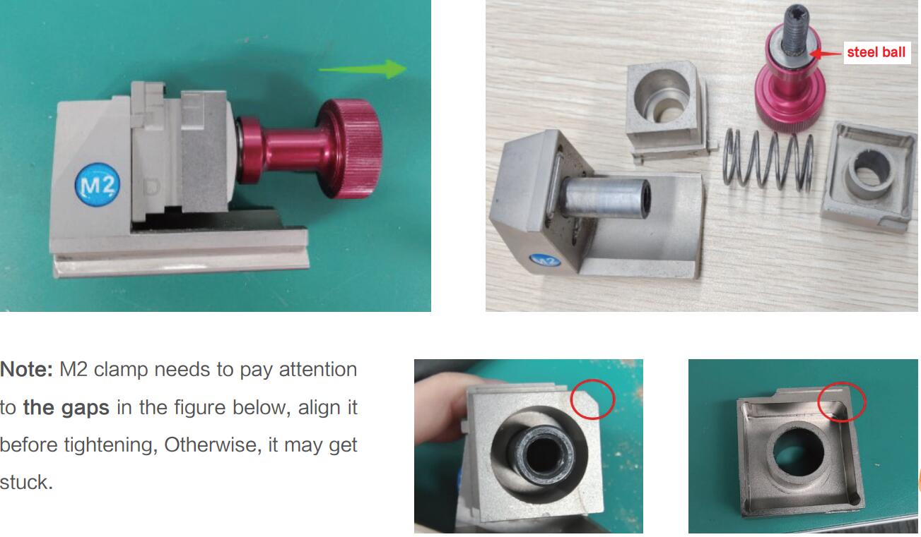
M2 clamp: Rotate the knob outward on the left picture, then it can be disassembled. Replace the corresponding parts according to the picture on the right.
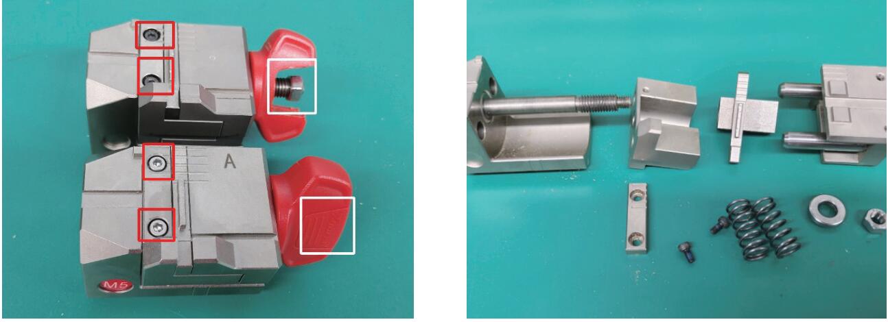
M5 clamp:Remove the nut in the white frame and remove the screws in the red frame on the picture below, rotate the knob outward on the left picture, then it can be disassembled. Replace the corresponding parts according to the picture on the right.
Tipt to Cut B119 Key Blank with Xhorse Dolphin XP005
Problem:
My friend has problems with the Xhorse dolphin xp005 key cutting machine. It’s not cutting b119 keys correctly. They look identical but only turn on door and not ignition.

Here are possible solutions:
1. Do a recalibrating. Recalibration should handle it,
Go into the app and calibrate it. Just did a couple b119 keys and it’s doing fine. Usually calibrate Dolphin once a month to stay on the safe side.
2. Make sure the original key if decoding from it with the machine that the key blade is clean of any dirt or debris this can cause a issue with improper read which results in only working one lock and not another.
3. Try universal duplication.
4. Upgrade to m5 clamp.
User Feedback:
Did recalibration. No luck. Change M5 clamp and M5 clamp worked.
Tips to Decode GM B106 Key Blank with Xhorse Dolphin XP005
Problem:
Anyone have problems with your machine decoding B106 key blank or any gm keys including old gm single side cut.? I can’t get my Triton or Xhorse Dolphin XP005 to decode them accurately? If I cut by code they work every time just won’t decode them. Any solution?

Possible solutions:
1. When can’t get Xhorse dolphin to decode something use the universal duplicator function to cut a key.
2. If the tip is worn they will read improper. You eyeball them and put it in fill to verify that it’s a good code.
3. Sight read. Decode with your eyes.
4. Get good at eyeballing the cuts on the key. B106 is easy. If the cut goes below the milling groove, then it’s a 5. if its at the milling groove, but doesn’t cut into it, it’s a 4. The rest you can figure out by how high or low they are relative to each other. You’re only really sight-reading 3 different depths at that point. Hold a blank key behind the worn out key if it helps you. If that still doesn’t help, buy a Lishi and decode the door lock to figure out over half of the cuts and sight-read the rest off of the blade. Use cuts-to-code software if you want to verify a valid cut combination.
If all of that fails, get the ignition to turn over once more. Usually the worn key just needs to be pulled out a tad, because the tip is worn down and give it the ol’ GM jiggle. Then pull the ignition and read the code or read the wafers inside.
How to Cut ZD24R Motorcycle Key with Xhorse Dolphin XP005?
Since I’ve used the ZD24R LISHI to pick and decode a Can-Am Spyder 3-wheel motocycle ignition, so next I’m going to cut the key with Xhorse Dolphin XP005 by bitting. In case to wreck a pretty expensive key blank, I would try X270 TMC1 key for a test at first. The bitting codes decoded by LISHI is 232234.
.jpg)
.jpg)
Cut by bitting >> Silca – ZD24R >> ZD24R, 6 bitting, 770*2350
M1 clamp Shoulder align.
This type recommend use 1.5mm to cut.
Press “OK”.
Input the bitting codes: 232234
Put and fix the key on M1 clamp according to prompts.
Cut key >> Cut
Dolphin XP005 machine starts cutting automatically.
Please wait…
.jpg)
.jpg)
.jpg)
.jpg)
.jpg)
Get the key out when cutting completed.
It’s working perfectly in ignition.
It should be noted in particular here this Can-Am ignition is from 2011 or 2012, it’s wide open and easy to get the keyway. The key can work with no problem at all.
But some of the newer ones starting like 2019/2020/2021, this black bezel here that actually covers most of this ring. So either have to pop that off or what I like to do is just to cut the head of key off.
When you try to put the key in, it stops on the bow of the key and it won’t go all the way in. So you may think your cuts are wrong. Just cut the whole head of key off, test it and make sure it’s working here before cutting.
This is how to cut ZD24R key with Dolphin successfully, you may use the newer Dolphin II Key Cutting Machine to do the job as well.
.jpg)
.jpg)
Xhorse Dolphin XP005 Fixed VA2EH2 Bug
Xhorse Condor Mini Plus/Condor II/Dolphin XP005/XP005L released a new database update on Nov. 7th, 2023.
Serial number and firmware version:
.jpg)
APP version: Android 4.1.5, iOS 4.1.5
Add key data
Kawasaki KLR
Xiaopeng P7
Luyuan Electric Vehicle
Automobile Weizhi V2
Kia K9
Yuejin S80
Geely Geometry E
Isuzu Competitor
Hyundai Tucson
Hyundai Santa Fe
Hyundai Xcient
Ruilan Maple 60S
Citroen C2
Pentium B70
Huasong 7
SINOTRUK Shandeka G5
Renault Clio
Chevrolet Captiva
Honda Motorcycle:
Wuyang Kaiying
Wuyang NBX1OO
Wuyang Baofengyan CB190R
Wuyang Biaoying 150
Wuyang Jiaying
Wuyang Xijun
Wuyang Joyful Little Princess
Wuyang New Fenchi
Wuyang New Xisha 125T
Wuyang New Youyue
Wuyang Fengxiang,
New Continent CBF19OR
New Continent Ruibiao 125
*Fix HY18R bug
*Fix HY18R bug
*Fixed VA2EH2 bug
*Fixed HU71 bug
*Fix other bugs.