ابزار Xhorse VVDI
Xhose VVDI نرم افزار برنامه نویس اصلی و سخت افزارابزار Xhorse VVDI
Xhose VVDI نرم افزار برنامه نویس اصلی و سخت افزارHow to program Benz ELV Simulator with VVDI MB Tool
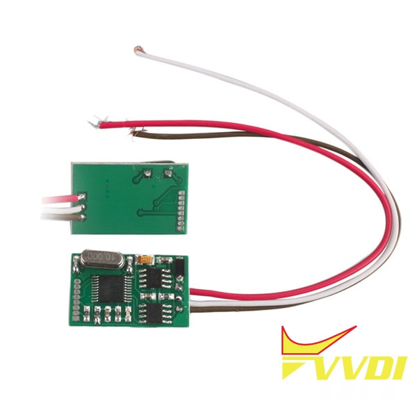
The Benz W204 W207 W212 ELV simulator MB KEY OBD2 is designed to work for all Mercedes C series, E series and GLK, including C180, C200, C280, E200, E260, E320 , E350, GLK200, GLK350 (from 2006 to 2014).
Chassis Number: W204, W207, W212
Chassis Number: W204, W207, W212
It can be programmed by MB key programmers, diagspeed, VVDI MB tool etc.

Note: The ELV simulator can be used on W204 W207 W212 chassis only when EIS not start.
It is can used on one EIS for one time only.
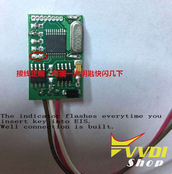
The indicator flashes for 2 seconds every time you insert key into EIS which means you have connected the simulator correctly.
Here’s the programming procedure using VVDI MB:
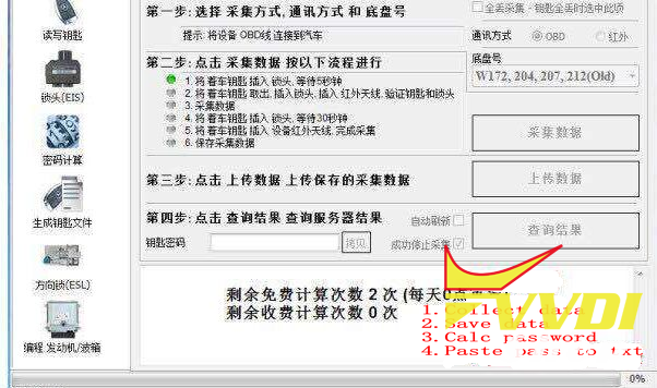
Step 1:
1.Collect data
2.Save data
3.Calculate password online
4.Paste password to notepad
2.Save data
3.Calculate password online
4.Paste password to notepad
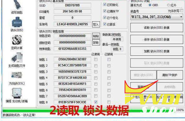
Step 2: Read EIS data
Step 3: Paste the key password here and save EIS data

Step 4:
1.Read EIS via IR
2. Erase EIS

Step 5:
EIS erased does not have VIN
Upload EIS data with password saved from step 3
Select OBD Write VIN
Select Write EIS via IR

Step 6:
1. Read EIS data
2. Personalize W204 ESL
3. Check the indicator on ELV simulator flashes for 2 seconds
Success.

How to Program BM,W 523i 2003 remote key with VVDI2
Car model: BMW 523i year 2003 E39

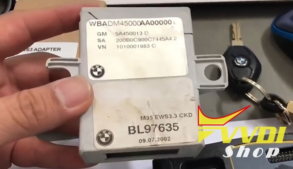
Immo box: EWS3
Purpose: Program chip and remote
Device:
Cut key by Condor XC-Mini
Program remote by VVDI Key Tool
Step 1: Read EWS3 Dump with VVDI Prog

EWS3 box read IC: 0D69J use EWS3 adapter +vvdi prog
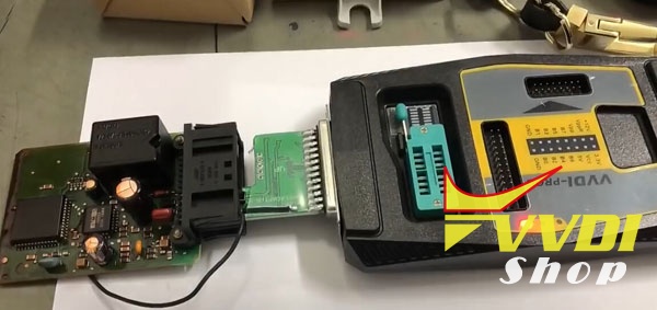
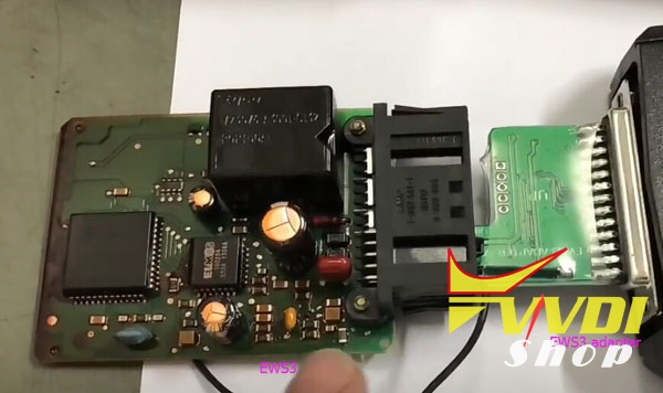
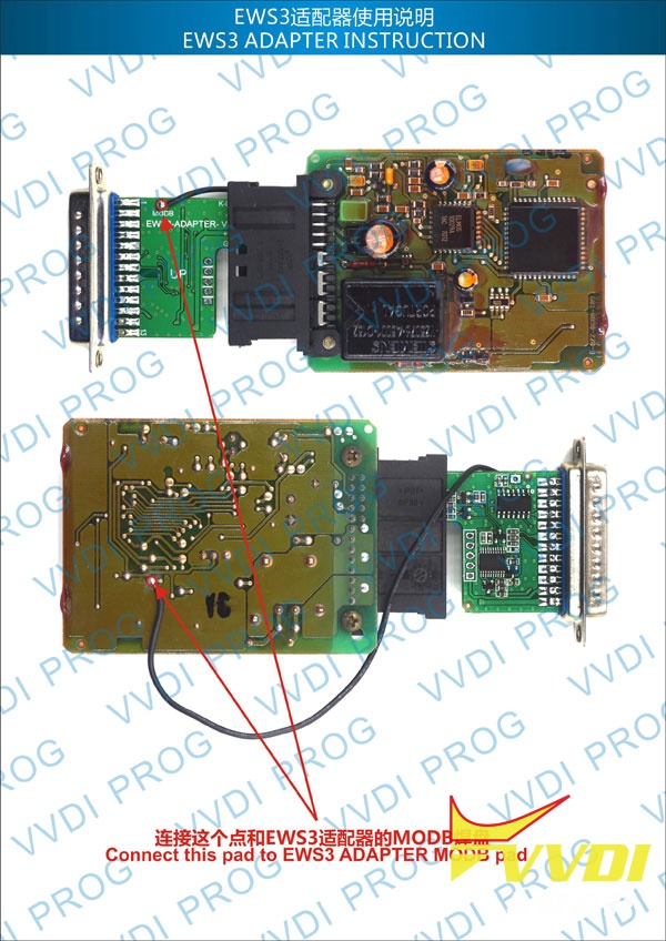
Connect EWS3 adapter and soldering cable same as diagram
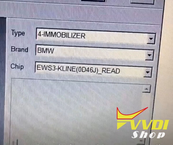
Select Immobilizer-BMW-EWS3-K-line (0D69J) Read
connect 12V DC to vvdi prog
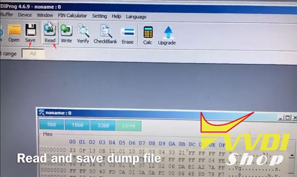
Read and save dump file
Step 2: Program dealer key with VVDI2 BMW
Connect Xhorse VVDI2 with laptop
Open VVDI2 software
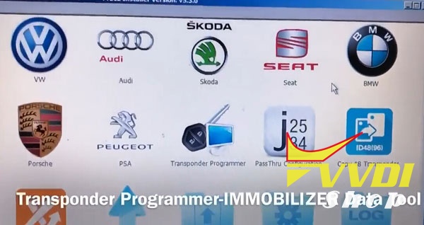
Select Transponder Programmer- Immobilizer Data Tool
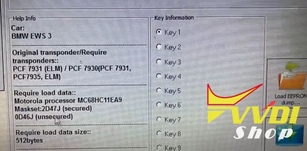
Load EEPROM dump read by vvdi-prog
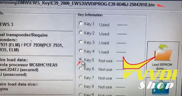
Select an unused key position and Make Dealer Key
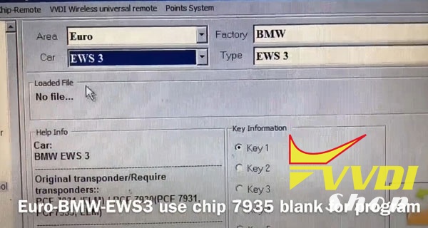
Select Euro-BMW-EWS3 use chip 7935 blank for program
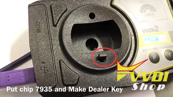
Put chip 7935 and make dealer key
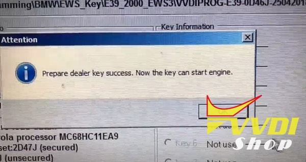
Prepare dealer key success.-key can start engine now.
Step 3: Cut key with Condor Mini

cut key by condor
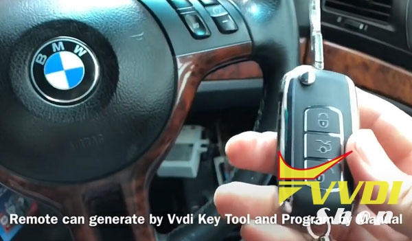
Step 4: Program Remote with Xhorse VVDI Key Tool
Remote can generated by vvdi key tool and program by manual
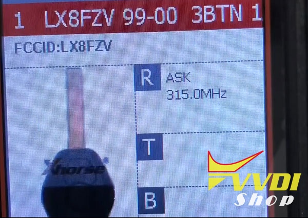
Generate remote with vvdi key tool
Install EWS3 box then try to start

Turn on for second to synchronize new key
Start success
Start success
Done!!!
How to activate Xhorse VVDI2 FULL MQB for free
Good News!!! Great gift from Xhorse. Since today vvdishop.com is able to enable for free MQB activation (VV-05) for all user who have VVDI2 Full. You can buy ID48 96bit cloning and get free MQB, but if you no need copy 48, you can request free MQB.
1.Just for oversea VVDI2 users.
2. Make sure your VVDI2 is full version
(VV-01)VAG 4th immobilizer YES
(VV-02)VAG 5th immobilizer YES
(VB-01)BMW OBD YES
(VB-02)BMW CAS4 YES
3. Provide your device Serial Number to our customer service.
Along with your full name, country, address, email and telephone number.
4. We’ll inform you when authorization is done.
5. Update your firmware and check free MQB activation.
Email: sales@VVDIShop.com
Skype: VVDIfactory.com
VVDI2 Change Odometer for Skoda Octavia 2015 MQB
Here’s an example of odometer (mileage) correction in the car Skoda Octavia 2015 (VAG MQB platform). The procedure is carried out with the Xhorse VVDI2 VAG key programmer.

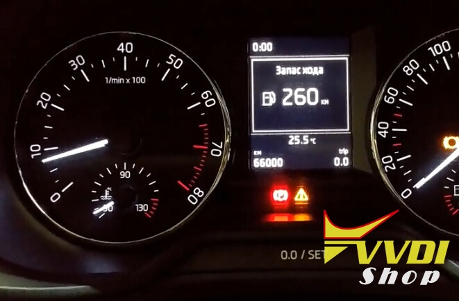
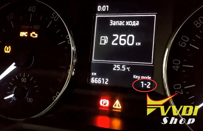
Original mileage: 66,612KM
Open VVDI2 software
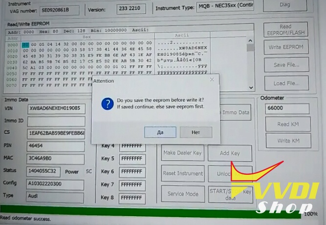
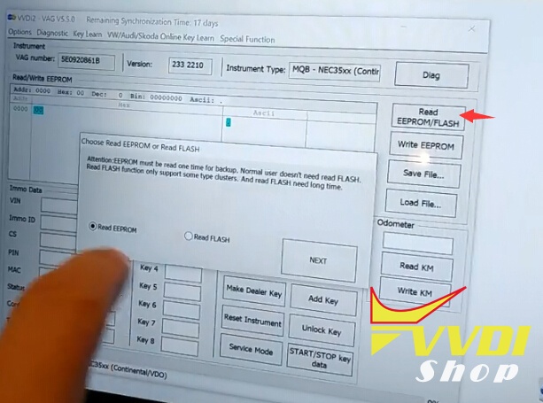
Select Key Learn->MQB platform instrument immobilizer->Instrument with NEC35xx (Continental/VDO)
Click on Diag to load vehicle information
Instrument version 2210
Instrument type: MQB NEC35xx Continental VDO
You can read eeprom and save it first.
Click on read KM

Read odometer success.
Manually enter odometer you desired

Click on Write KM
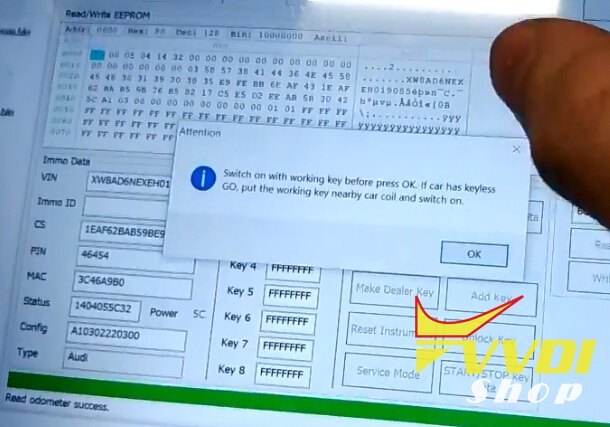
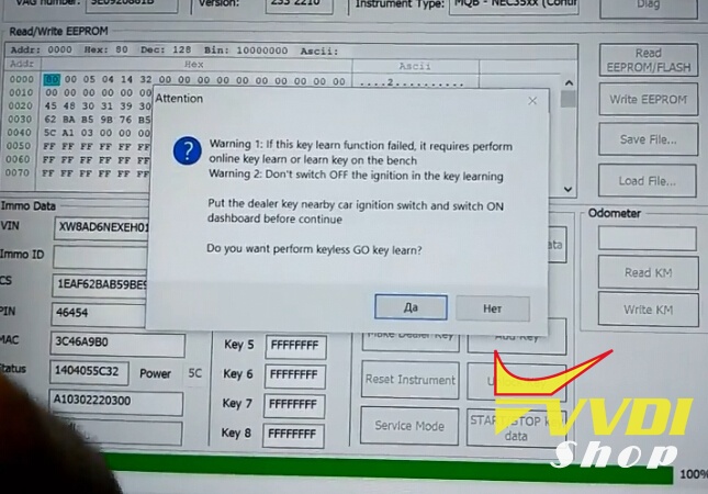
Switch ignition on with working key before press OK. If car has Keyless Go, put the working key nearly car coil and switch on.
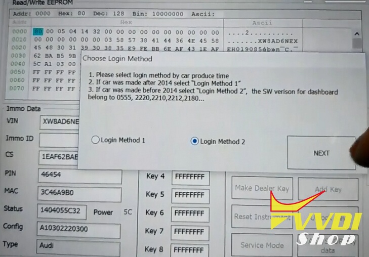
Choose security login: Login Method 2 (because software version of the dashboard belong to 2210)
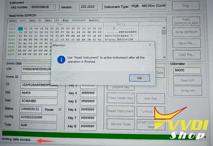
Write data success.
Use “Reset instrument” to active instrument after all the operation is finished.

Reset success.

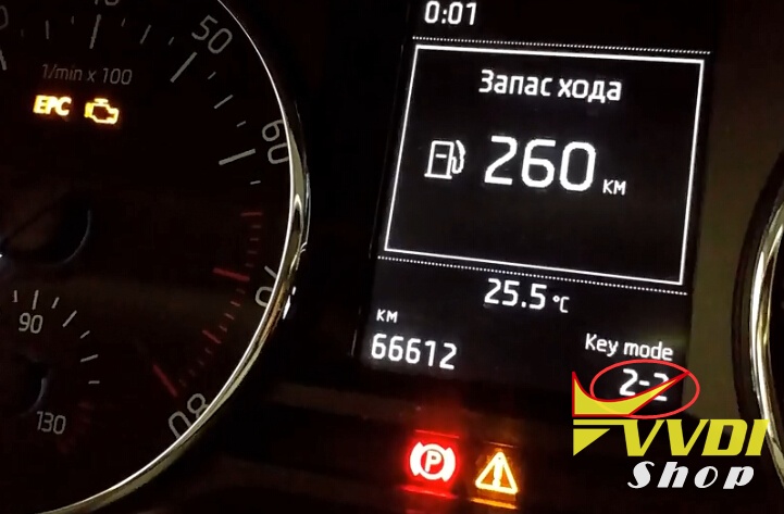
Check mileage on dashboard
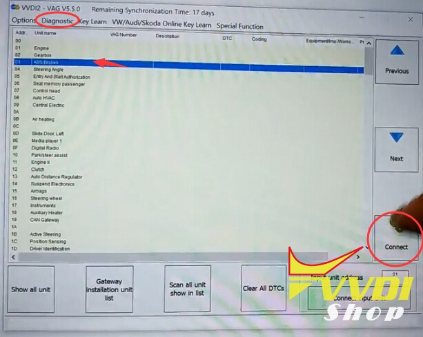
Clear ABS fault codes with VVDI2 software

Done.
http://blog.vvdishop.com/vvdi2-change-mileage-on-skoda-octavia-2015-mqb-system/
VVDI2 VAG Program Skoda Octavia 2015 MQB Smart Key
Here’s an example of programming a smart key in the car Skoda Octavia 2015 (MQB platform VAG) using Xhorse VVDI2 VAG key programmer.
Open VVDI2 VAG software
Select Key Learn->MQB platform instrument immobilizer->Instrument with NEC35xx (Continental/VDO)

Click on Diag to load vehicle information
Instrument version 2210
Instrument type: MQB NEC35xx Continental VDO
Read EEPROM data and save
Switch on with working key before press ok

If car has keyless Go, put the working key nearby car coil and switch on
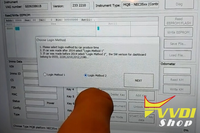
Choose Login Method 2, the car software for dashboard belong to 2210
Press Next to continue
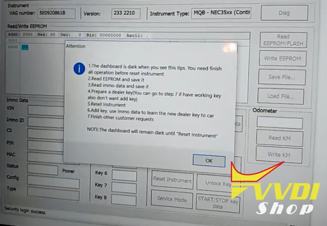
1. The dashboard is dark when you see this tips. You need finish all operation before reset instrument.
2.Read EEPROM and save it.
3.Read IMMO data and save it.
4. Prepare a dealer key (You can go to step 7 if have working key aslo
don’t want to add key)
5. Reset instrument
6. Add key use immo data to learn the new dealer key to car
7. Finish other customer requests.
Save eeprom
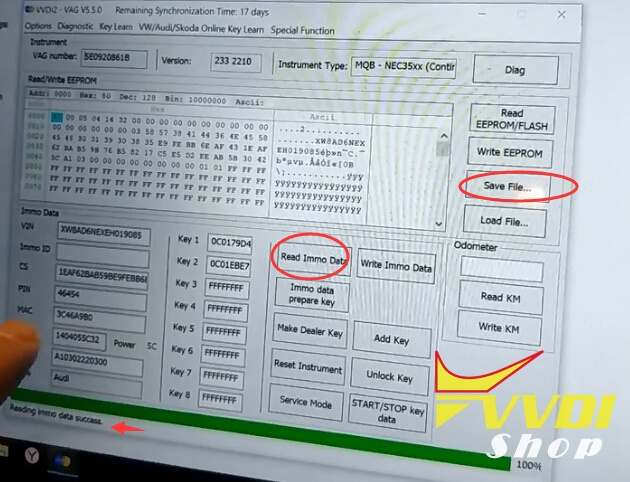
Click on Read Immo data and then save it
Select Maker Dealer Key->Skoda
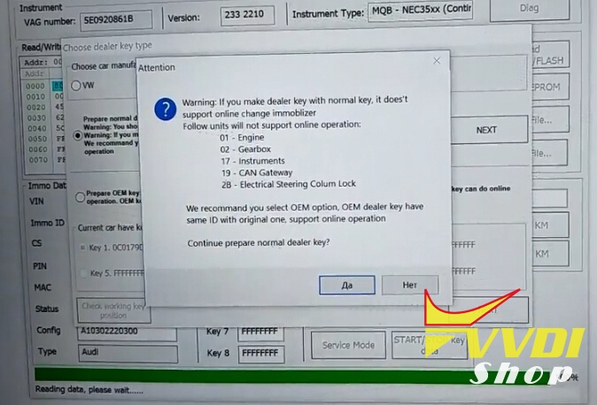
If prepare normal dealer key, follow instructions below:
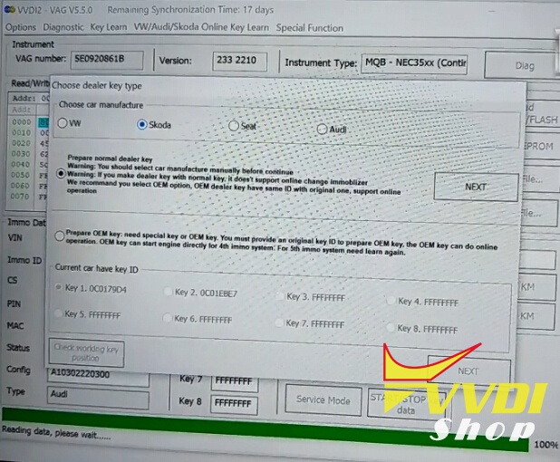
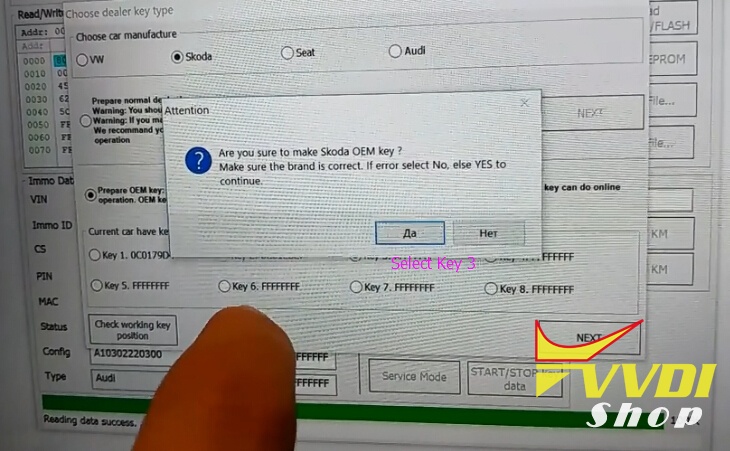
Here we select Prepare OEM key
Prepare OEM key: need special key or OEM key. You must provide an original key ID to prepare OEM key. The OEM key can do online operation. OEM key can start engine directly for 4th immo system.
For 5th immo system need learn again.
For 5th immo system need learn again.
Select key position 3
Press Next to continue
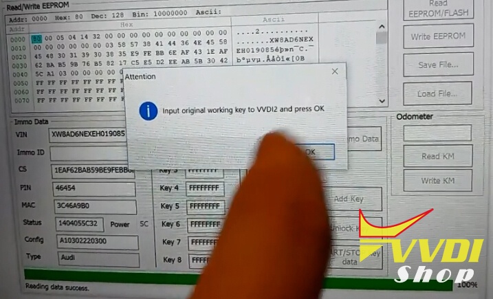
Input original working key to VVDI2 and press OK
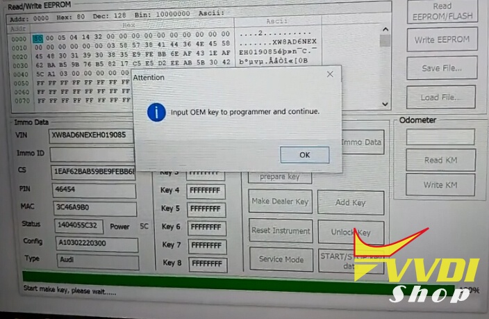
Input OEM key to VVDI2 key programmer and continue.

Use “Reset instrument” to active instrument after all the operation is finished.
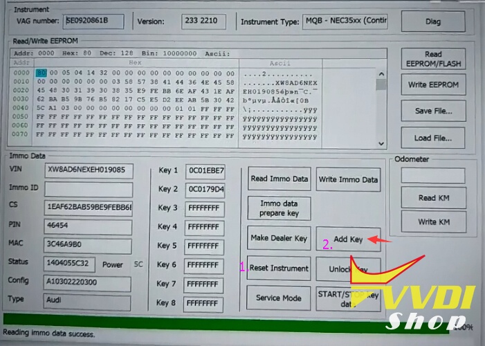
Click on Add key
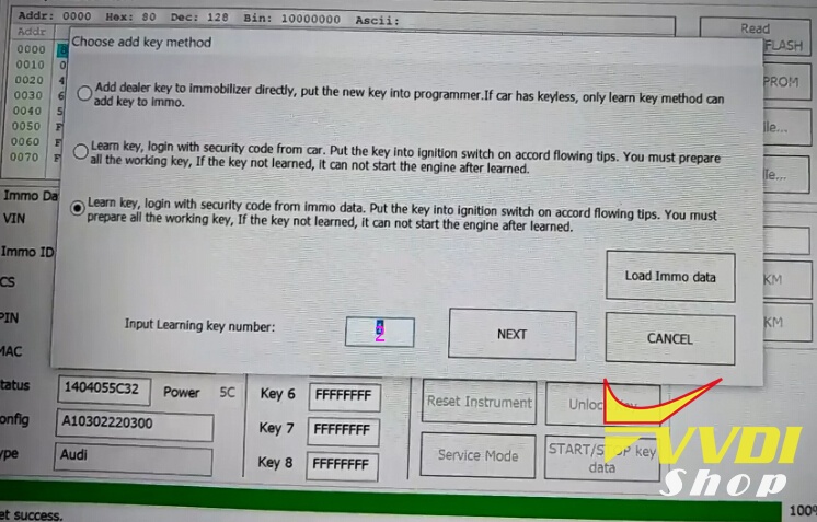
Select Learn key, login with security code from immo data. Put the key into ignition switch on accord flowing tips. You must prepare all the working key.
Select key number to learn: 2
Press Next
Select key number to learn: 2
Press Next
Confirm car has keyless.
Put the dealer key nearby car ignition switch and switch ON dashboard before continue
First key learn succeed
Learn second key with VVDI2
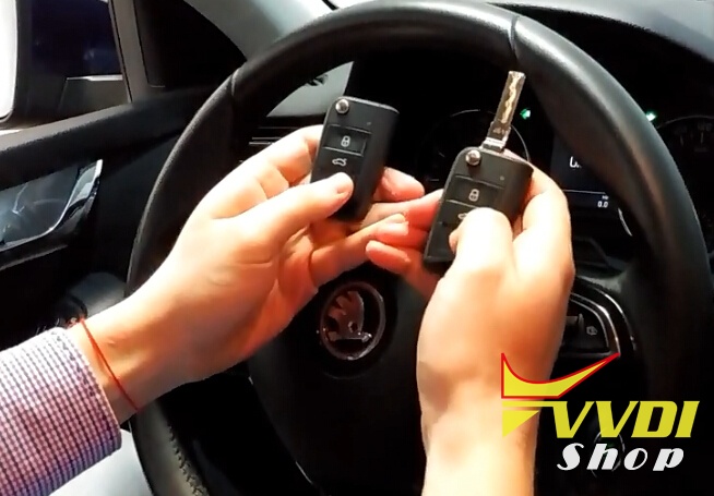
Test the remote control and start car.
Success.