ابزار Xhorse VVDI
Xhose VVDI نرم افزار برنامه نویس اصلی و سخت افزارابزار Xhorse VVDI
Xhose VVDI نرم افزار برنامه نویس اصلی و سخت افزارTest Xhorse Dolphin XP005 Probe and Cutter Conductivity
Here is the tip on detecting abnormal conductivity of xhorse dolphin xp005 key cutting machine probe and milling cutter.
Step 1: Disassemble the back cover, and be careful of the wiring harness of the cover when disassembling
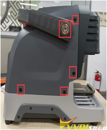
Step 2:
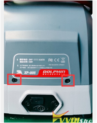
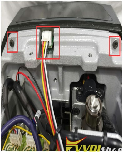
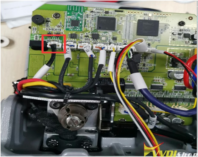
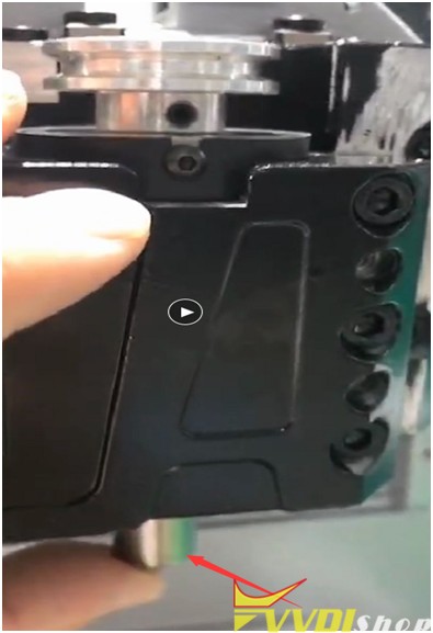
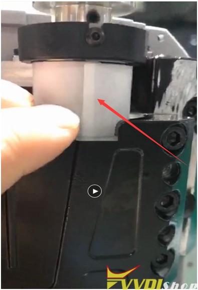
Remove the back cover, you can see these things, take off the wire harness, and remove the Phillips screws (see Figure 1). Take out the rubber pellets from the front of the device. There are screws inside. This strip needs to be removed (Figure 2)
(Figure1)
(Figure2)
Step 3:
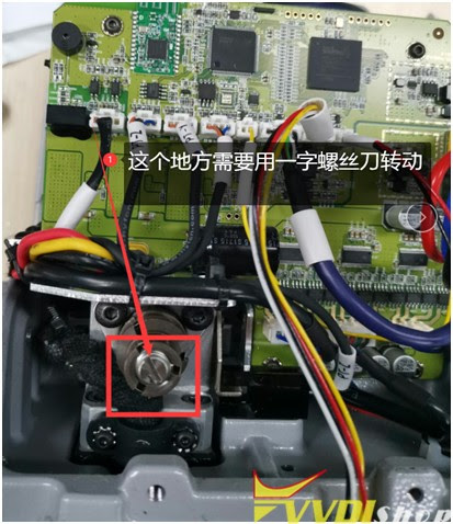
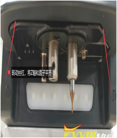
Use a flat-blade screwdriver to turn the lead screw, align the Z-axis and the outer cover on a horizontal surface (as shown in Figure 3 and Figure 4), remove the Z-axis housing after alignment (as shown in Figure 5), and place the probe next to it. Remove the screws (as shown in Figure 6). Remember to be careful when removing it. There is a conductive wire inside (as shown in Figure 7).
(Figure3)
(Figure4)
(Figure5)
(Figure6)
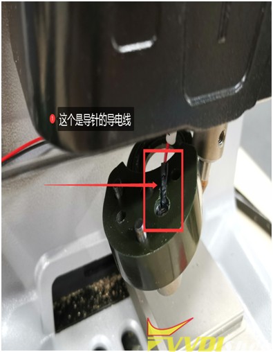
(Figure7)
Step 4:
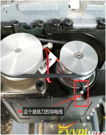
If the above steps are all done, the next step is to check whether the conductive wires of the milling cutter and the probe are conductive or short (as shown in Figure 5 and Figure 7), which needs to be combined with the main board to detect. (Figure 8) (or plug in the cable on the main board, and then check whether the conductivity is normal)
(Figure8)
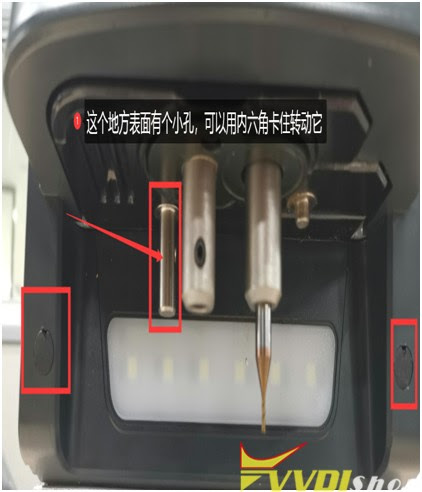
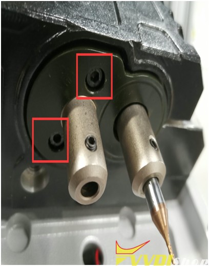
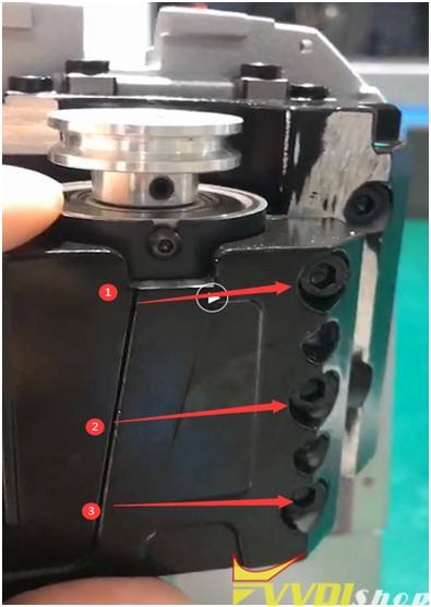
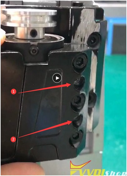
Step 5: (conductivity of cutter): Loosen the 3 screws of the Z axis (as shown in Figure 9), and then tighten the two screws (as shown in Figure 10). Push these two screws to the inside until there is a gap. This is to take out the shaft (as shown in Figure 11), press your finger on the position of the milling cutter hole, and push it up with a little force. Come up, and then observe whether the white paper inside is broken (as shown in Figure 12), if it is broken, it needs to be replaced. If it is not broken, observe whether there is iron filings in the bearing hole
(Figure 9)
(Figure10)
(Figure11)
(Figure12)
Any questions feel free to contact us.
https://www.vvdishop.com/service/test-xhorse-dolphin-xp005-probe-cutter-conductivity.html
Program BMW 320D 2006 CAS2 Remote with Xhorse Key Tool Plus
ow to use Xhorse VVDI Key Tool Plus to add a BMW 320D 2006 CAS2 remote key via OBD successfully in 2 minutes?
- Read & Save Data
Plug the connector into OBD2 port, press
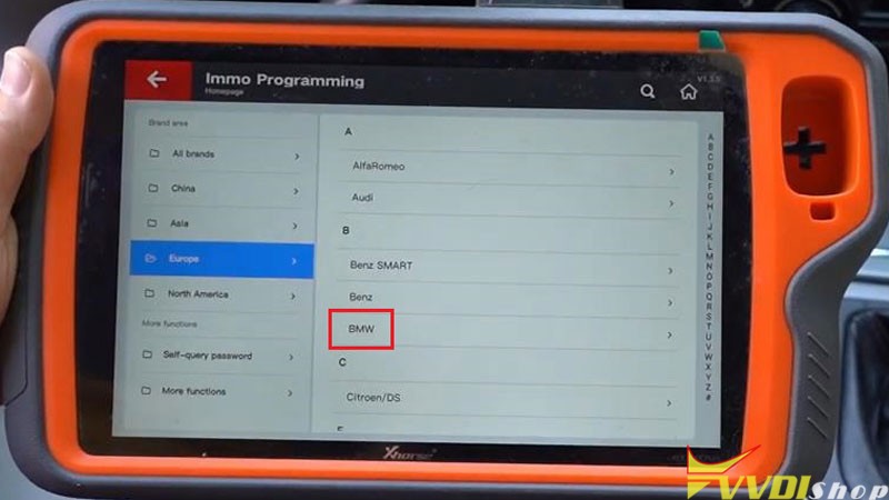
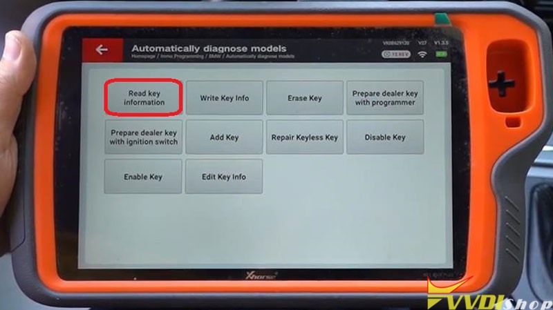
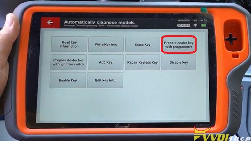
Immo programming >> Europe >> BMW >> Automatically diagnose models >> Start programming >> Read key information
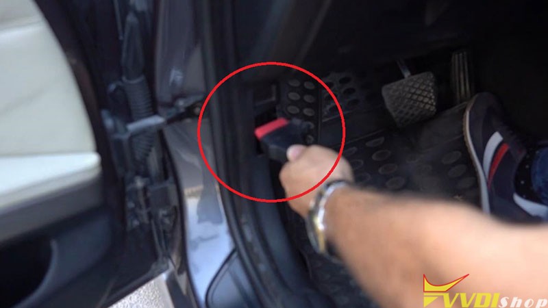
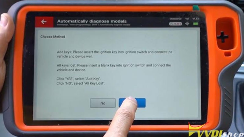
Insert the ignition key into ignition switch and connect the vehicle and device well.
Yes >> Yes
The dealer key should be taken away from ignition switch.
If key is keyless, please move it out of car.
If there’s no key in ignition, continue anyway.
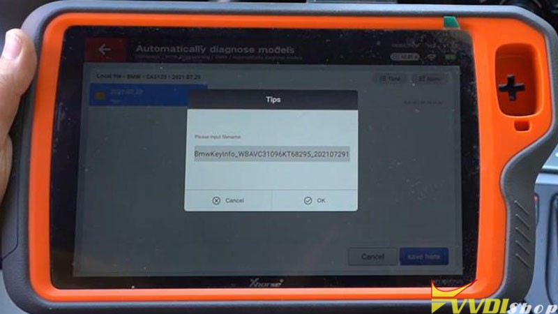
Save >> Save here >> Rename, OK
- Program New Key
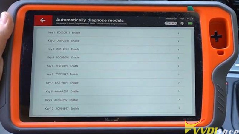
Prepare dealer key with programmer >> Select an enable key position:Key 10
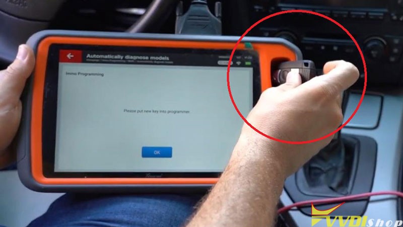
Put the new key into VVDI Key Tool Plus programmer.
Is the current key the smart key? No
Key make okay and locked. Please use it to start the car.
If can not start engine, use “Add key” function add the dealer key to CAS system.
If key can start engine, but keyless not working, use “Repair Keyless Key” function.
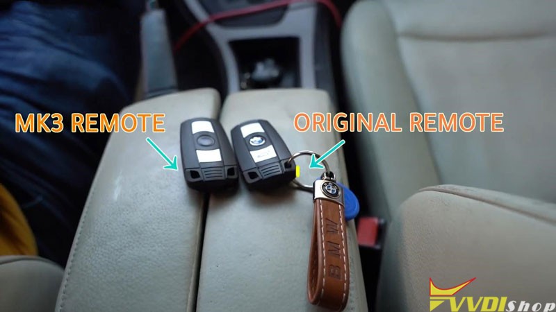
- Test Key
Test the new key now, it can start the engine, and its remote is workable.
Key adding has done!

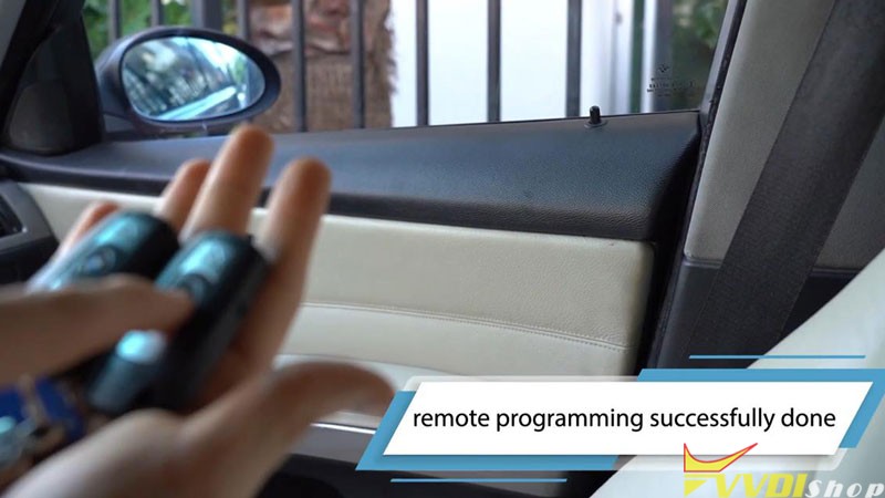
BMW 320D 2006 CAS2 remote key adding via Xhorse VVDI Key Tool Plus Pad is successful. Quite easy to be done in 2 minutes.
How to Add M3 2011 CAS3+ Key with Xhorse Key Tool Max
How-to: BMW M3 2011 CAS3+ ISTAP 0L15Y spare key programming with xhorse mini prog and key tool max.
1.Read EEPROM with VVDI Mini Prog
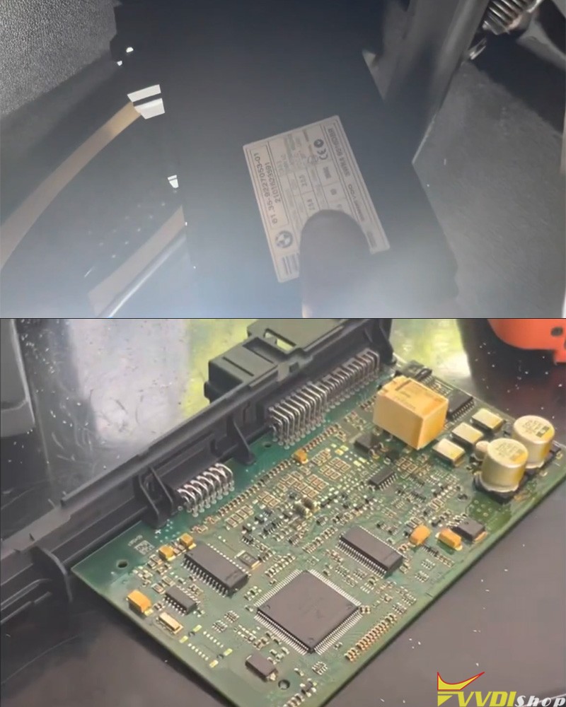
Remove CAS3+ Module
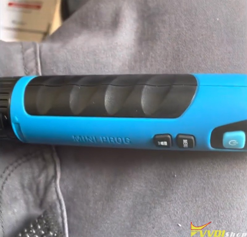

Connect mini prog CAS3 solder free adapter with CAS3 module
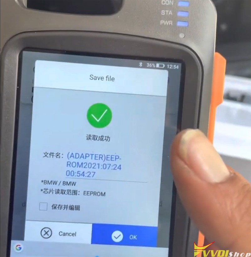
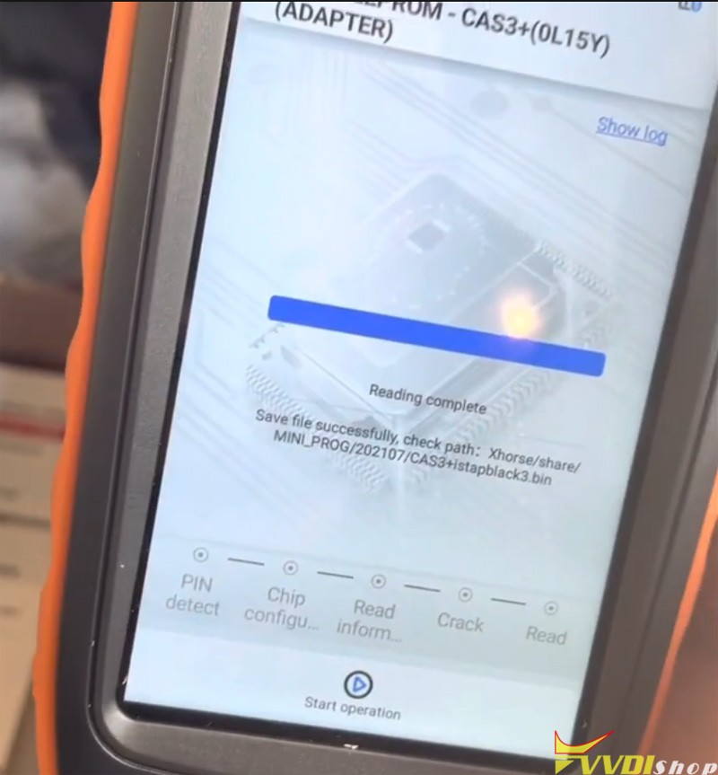
Follow mini prog app prompts to read EEPROM and save data
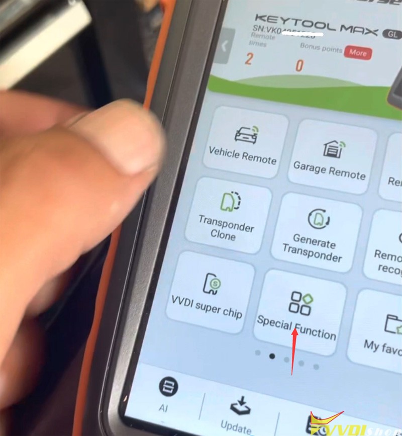
2.Make dealer key with xhorse vvdi key tool max
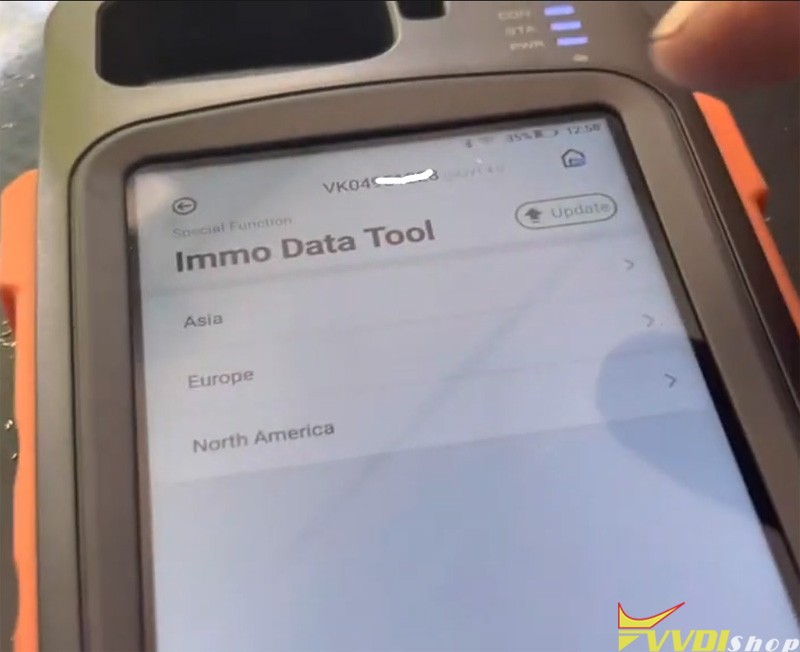
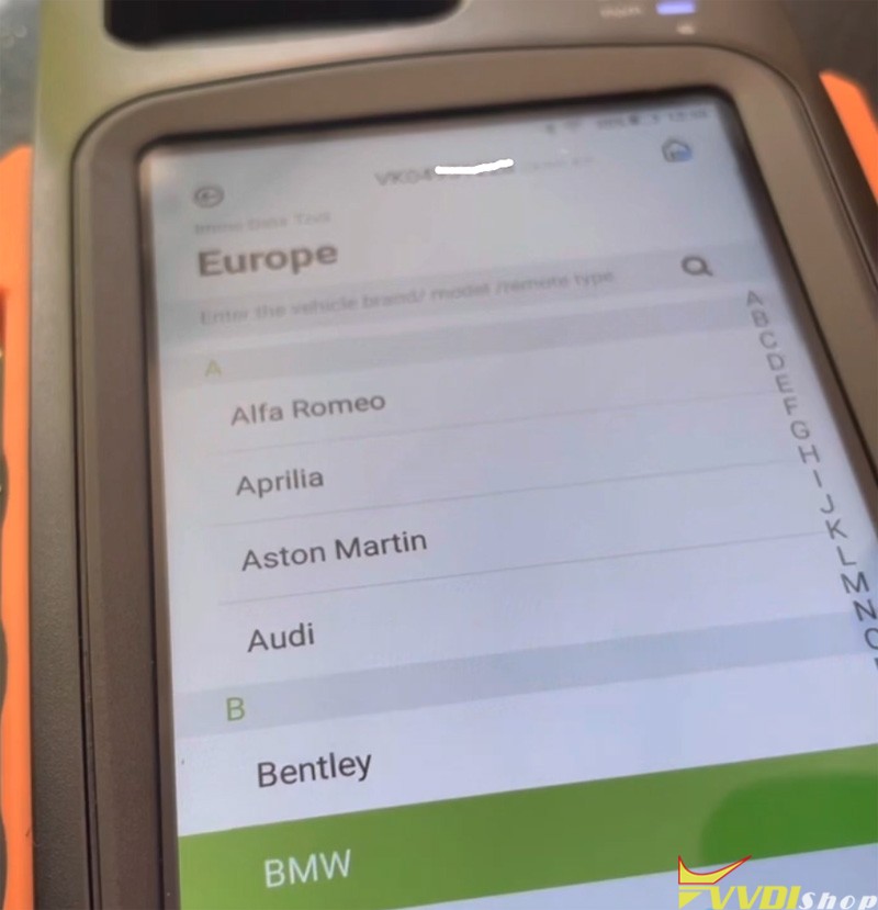
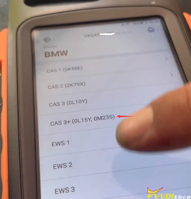
In key tool max app, select Special function -Immo data tool- BMW- CAS3+ 0L15Y
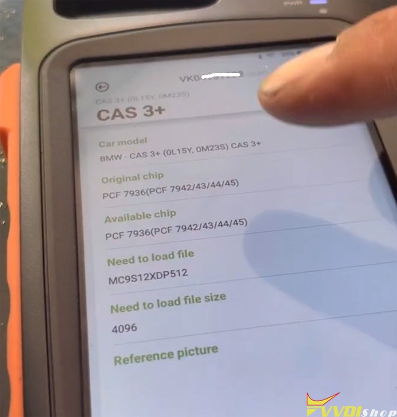
Then load eeprom read by the mini prog
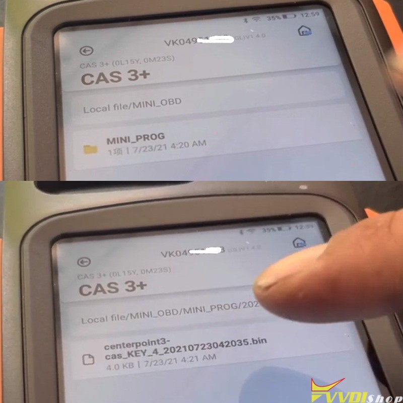
Write key with dump
Reinstall CAS3+ module.
Test new key and remote control.
Done.